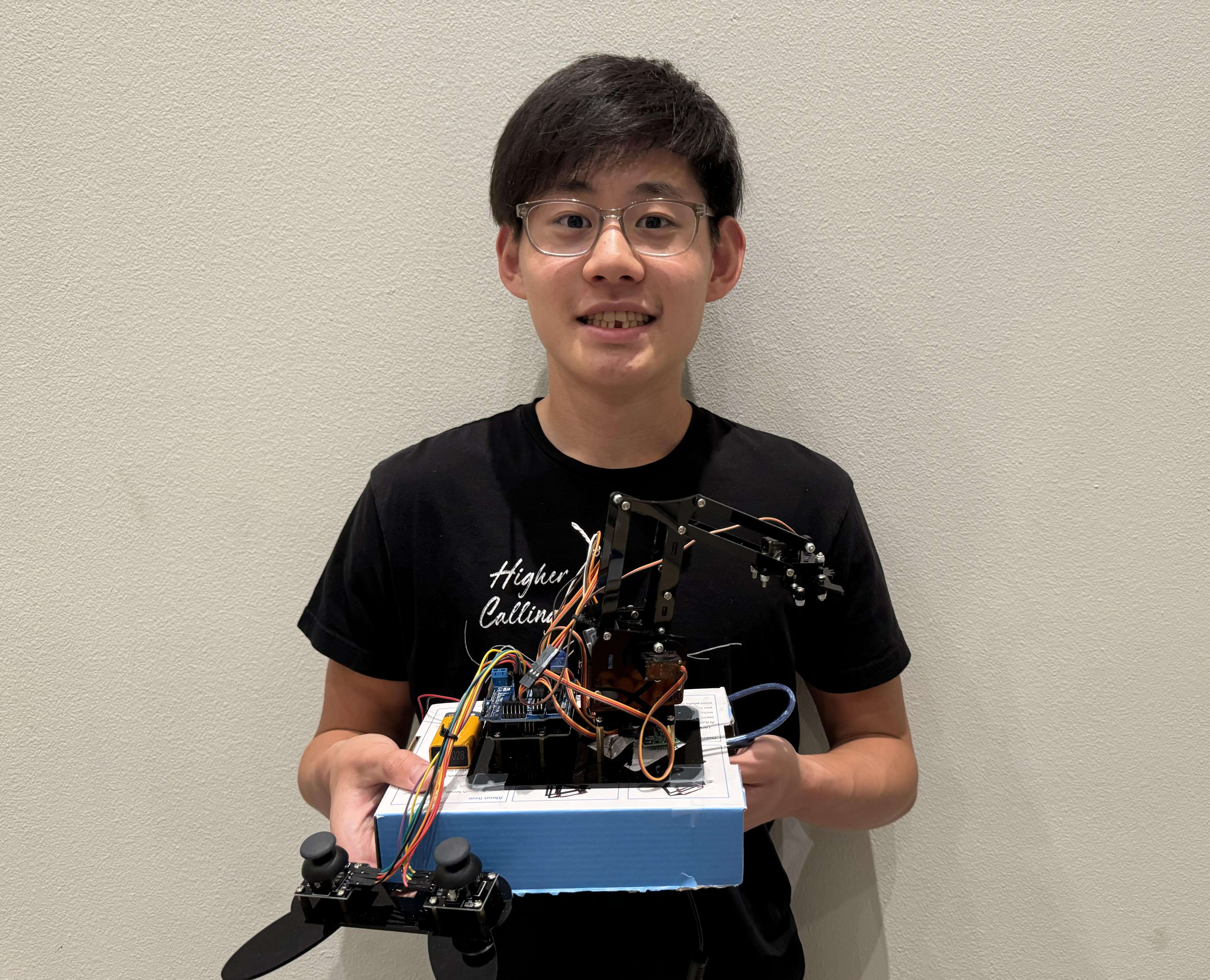
3-Joint Robotic Arm
My project is a 3-joint robotic arm that uses four servo motors to control four ranges of motion. The robotic arm is able to move side to side, up and down, forward and backward, and pick up objects. The servo motors are powered by a sensor shield and are controlled using the x and y axes on two joysticks of a controller.
| Engineer | School | Area of Interest | Grade |
|---|---|---|---|
| Martin C | Troy High School | Mechatronics Engineering | Junior |
Final Milestone
Final Milestone Key Details:
-
For my final milestone, I added bluetooth to my robotic arm. To do this, I connected an HM10 bluetooth module to my Arduino and started software serial communication between the Arduino and HM10 so the components can communicate with one another. This allows me to send inputs from my phone, which in turn sends signals to the HM10, and then the Arduino. Additionally, I connected a Raspberry Pi 4 to my Arduino via USB and started serial communication between the two. This allowed me to send signals from the Arduino’s joysticks to the Raspberry Pi’s camera to take pictures at the click of the joystick button.
-
My biggest challenge at Bluestamp was figuring out how to send data between my Arduino and Raspberry Pi for my camera. Raspberry Pi 4 no longer supports the latest version of Arduino IDE, which means that there weren’t many relevant online resources to help me. I solved this issue by downloading a previous version of Arduino and combining bits of code from various youtube guides, online forums, and Bluestamp instructors. My biggest triump is getting the camera to finally work with the Arduino because I spent so many hours researching for it.
-
At Bluestamp, I gained hands-on experience with engineering and learned how to break down big projects into smaller steps. The three joint arm seemed intimidating at first, but wasn’t as difficult as I thought it would be once I started working on it.
Final Milestone Code
#Code for Raspberry Pi camera
from picamera2 import Picamera2, Preview
import time
import cv2
import serial

ser = serial.Serial('/dev/ttyACM0', 9600, timeout=1.0)   #connects pi serial to arduino serial
time.sleep(2)               #waits 3 seconds to allow arduino to set up serial communication
ser.reset_input_buffer()               #resets serial communication data received within 3 sec sleep
print("Serial OK")        #prints if everything is fine with no error

camera = Picamera2()
camera.start(show_preview=True)

try:          #try/except structure is like while loop w/ "except" that can handle error cases.
    while True:
        time.sleep(0.01)
        if ser.in_waiting > 0:    #ser.in_waiting returns number of bytes in serial monitor.
            line = ser.readline().decode('utf-8')   #reads line until end of current line
            print(line)
            if "Taking Picture" in line:
                im = camera.capture_array()
                current = time.ctime(time.time())       #display current time for each photo taken. Creates new files for photos instead of replacing the same file with consequent photos.
                cv2.imwrite(current + ' photo.png', im)
except KeyboardInterrupt:
    print("Close Serial Communication")
    ser.close()            #closes serial communication before program is terminated.
//I added this procedure to the second milestone code to allow for taking pictures.
void picture(){
  if (digitalRead(left_key)==LOW){
    Serial.println("Taking Picture");
    delay(300);
  }
}
//This is the code for the HM10 bluetooth module. A software serial object is created to emulate a physical connection between the HM10 and Arduino.
#include <SoftwareSerial.h>
#include <Servo.h> // add the servo libraries
Servo myservo1; // create servo object to control a servo
Servo myservo2;
Servo myservo3;
Servo myservo4;
int pos1=90, pos2=90, pos3=90, pos4=90; // define the variable of 4 servo angle,and assign the initial value (that is the boot posture
//angle value)

//Create software serial object to communicate with HM10
SoftwareSerial mySerial(13, 12); //HM10 Tx & Rx is connected to Arduino #13 & #12.  emulates serial communications pins 1 and 2.
//*transmit/receive of arduino is flipped from transmit/receive of bluetooth module.

void setup()
{
  // boot posture
  myservo1.write(pos1);
  delay(1000);
  myservo2.write(pos2);
  myservo3.write(pos3);
  myservo4.write(pos4);
  delay(1500);
  //Begin serial communication with Arduino and Arduino IDE (Serial Monitor)
  Serial.begin(9600);

  //Begin serial communication with Arduino and HM10
  mySerial.begin(9600);
}
char serial_val;

void loop()
{
  myservo1.attach(3); // set the control pin of servo 1 to D3  dizuo-servo1-3
  myservo2.attach(5); // set the control pin of servo 2 to D5  arm-servo2-5
  myservo3.attach(6); //set the control pin of servo 3 to D6   lower arm-servo-6
  myservo4.attach(9); // set the control pin of servo 4 to D9  claw-servo-9
  if(mySerial.available())
  {
    serial_val = mySerial.read();//Forward what Software Serial received to Serial Port
    Serial.write(serial_val);
    switch(serial_val)     //switch is like compact if statements.  The "case" statements are like separate if statements. Ex. If we send "L", T_left() will run.
    //after checking a case, arduino will move on to check next case (hence the "break" after each line.)
    {
      case 'L':  T_left();  break;   // turn left
      case 'R':  T_right();  break;//turn right
      case 'B':  RB();  break;// the lower arm will draw back
      case 'F':  RF();  break;// the lower arm will  stretch out
      case 'C':  ZK();  break;//close the claw
      case 'O':  ZB();  break;//open the claw
      case 'U':  LB();  break;//the upper arm will lift up
      case 'D':  LF();  break;//the upper arm will go down
      case 'P':  pickUp(); break;//arm will close claw and lift object
      default:break;
    }
  }
  delay(20);
}
//**************************************************
void pickUp(){
  while (pos4 > 10){
    ZK();
    delay(75);
  }
  delay(500);
  for (int i=0; i<4; i++){
    LB();
    RB();
    delay(50);
  }
}

// turn left
void T_left()
{
    pos1=pos1+8;
    myservo1.write(pos1);
    delay(5);
    if(pos1>180)
    {
      pos1=180;
    }
}
//turn right
void T_right()
{
    pos1=pos1-8;
    myservo1.write(pos1);
    delay(5);
    if(pos1<1)
    {
      pos1=1;
    }
}
//********************************************
//close the claw
void ZK()
{
      pos4=pos4-8;
      Serial.println(pos4);
      myservo4.write(pos4);
      delay(5);
      if(pos4<10)
      {
        pos4=10;
      }
}
// open the claw
void ZB()
{
    pos4=pos4+8;
    Serial.println(pos4);
    myservo4.write(pos4);
    delay(5);
    if(pos4>120)
    {
      pos4=120;
    }
}
//******************************************
// the lower arm will draw back
void RB()
{
    pos2=pos2-8;
    myservo2.write(pos2);
    delay(5);
    if(pos2<25)
    {
      pos2=25;
    }
}
// the lower arm will stretch out
void RF()
{
    pos2=pos2+8;
    myservo2.write(pos2);
    delay(5);
    if(pos2>180)
    {
      pos2=180;
    }
}
//***************************************
//the upper arm will lift up
void LB()
{
  pos3=pos3+8;
  myservo3.write(pos3);
  delay(5);
  if(pos3>135)
  {
    pos3=135;
  }
}
//the upper arm will go down
void LF()
{
  pos3=pos3-8;
    myservo3.write(pos3);
    delay(5);
    if(pos3<0)
    {
      pos3=0;
    }
}
Second Milestone
Second Milestone Key Details:
-
For this milestone, I completed the assembly of the robotic arm and finished the code. The code works by constantly reading values from the joysticks using a while-loop and then executing the appropriate function to move the robotic arm.
-
What surprised me so far is the simplicity and efficiency of the base robotic arm. The only electrical components were four servo motors and two joysticks, which meant I only needed two unique blocks of code (and a lot of rinse & repeat).
-
A challenge I faced was that the robotic arm wouldn’t move when I input commands to the joysticks. I later realized that the screws on the moving joints were too tight and caused a lot of friction, so I loosened the screws at joints and the robotic arm began to move smoothly.
-
For my final milestone, I plan to add bluetooth capabilities to the robotic arm as an alternative to the joystick controller. I also plan on connecting a camera to the robotic arm so that I can take pictures and see what the robotic arm sees.
Second Milestone Code
#include <Servo.h> // add the servo libraries
Servo myservo1; // create servo object to control a servo
Servo myservo2;
Servo myservo3;
Servo myservo4;
int pos1=90, pos2=90, pos3=90, pos4=90; // define the variable of 4 servo angle,and assign the initial value (that is the boot posture
//angle value)
const int right_X = A2; // define the right X pin to A2
const int right_Y = A5; // define the right Y pin to A5
const int right_key = 7; // define the right key pin to 7(that is the value of Z)
const int left_X = A3; // define the left X pin to A3
const int left_Y = A4; // define the left X pin to A4
const int left_key = 8; //define the left key pin to 8(that is the value of Z)
int x1,y1,z1; // define the variable, used to save the joystick value it read.
int x2,y2,z2;

void setup()
{
// boot posture
  myservo1.write(pos1);
  delay(1000);
  myservo2.write(pos2);
  myservo3.write(pos3);
  myservo4.write(pos4);
  delay(1500);
  pinMode(right_key, INPUT); // set the right/left key to INPUT
  pinMode(left_key, INPUT);
  Serial.begin(9600); // set the baud rate to 9600
}

void loop()
{
  myservo1.attach(3); // set the control pin of servo 1 to D3  dizuo-servo1-3
  myservo2.attach(5); // set the control pin of servo 2 to D5  arm-servo2-5
  myservo3.attach(6); //set the control pin of servo 3 to D6   lower arm-servo-6
  myservo4.attach(9); // set the control pin of servo 4 to D9  claw-servo-9
  x2 = analogRead(right_X); //read the right X value
  y2 = analogRead(right_Y); // read the right Y value
  z2 = digitalRead(right_key); //// read the right Z value
  x1 = analogRead(left_X); //read the left X value
  y1 = analogRead(left_Y); //read the left Y value
  z1 = digitalRead(left_key); // read the left Z value
  //delay(5); // lower the speed overall

  // claw
  claw();
  // rotate
  turn();
  // upper arm
  upper_arm();
  //lower arm
  lower_arm();
}

//claw//
void claw()
{
  //claw
  if(x1<50) // if push the left joystick to the right
  {
    pos4=pos4+3;
    myservo4.write(pos4); //servo 4 operates the motion, the claw gradually opens.
    delay(15);

    if(pos4>120) //limit the largest angle when open the claw
    {
      pos4=120;
    }
  }

  if(x1>1000) ////if push the right joystick to the left
  {
    pos4=pos4-3;
    myservo4.write(pos4); // servo 4 operates the action, claw is gradually closed.
    delay(15);
    if(pos4<45) //
    {
      pos4=45; //limit the largest angle when close the claw
    }
  }
}

// turn//
void turn()
{
  if(x2<50) //if push the right joystick to the let
  {
    pos1=pos1+3;
    myservo1.write(pos1); // arm turns left
    delay(18);
    if(pos1>180) //limit the angle when turn right
    {
      pos1=180;
    }
  }

  if(x2>1000) // if push the right joystick to the right
  {
    pos1=pos1-3;
    myservo1.write(pos1); //servo 1 operates the motion, the arm turns right.
    delay(18);
    if(pos1<1) // limit the angle when turn left
    {
      pos1=1;
    }
  }
}

// lower arm//
void lower_arm()
{
  if(y2>1000) // if push the right joystick downward
  {
    pos2=pos2-2;
    myservo2.write(pos2); // lower arm will draw back
    delay(15);
    if(pos2<25) // limit the retracted angle
    {
      pos2=25;
    }
  }

  if(y2<50) // if push the right joystick upward
  {
    pos2=pos2+2;
    myservo2.write(pos2); // lower arm will stretch out
    delay(15);
    if(pos2>180) // limit the stretched angle
    {
      pos2=180;
    }
  }
}

//upper arm//
void upper_arm()
{
  if(y1<50) // if push the left joystick downward
  {
    pos3=pos3-2;
    myservo3.write(pos3); // upper arm will go down
    delay(15);
    if(pos3<1) //  limit the angle when go down
    {
      pos3=1;
    }
  }
  if(y1>1000) // if push the left joystick upward
  {
    pos3=pos3+2;
    myservo3.write(pos3); // the upper arm will lift
    delay(15);
    if(pos3>135) //limit the lifting angle
    {
      pos3=135;
    }
  }
}
First Milestone
First Milestone Key Details:
-
The robotic arm consists of an acrylic frame that is controlled using two joysticks that send input signals to the Arduino Uno board. The code on the Arduino IDE then takes this signal and converts it into a command for the servo motors to execute, such as moving the arm left 30 degrees. The servo motors are attached to the acrylic frame of the robotic arm and are powered by a sensor shield that is placed on top of the Arduino Uno’s pins.
-
For the first milestone, I plan on testing my servo motors and joysticks so I don’t have problems later that cause me to dissasemble the whole arm.
-
One minor challenge I faced was Arduino repeatedly giving me error messages when uploading code, but this was easily fixed by restarting my Arduino IDE.
-
For my second milestone, I plan on completing the assembly and code for the robotic arm.
First Milestone Code
//Setting up 4 servo motors
#include <Servo.h>
Servo myservo1; // create servo object to control a servo
Servo myservo2;
Servo myservo3;
Servo myservo4;
int pos1=90, pos2=90, pos3=90, pos4=90; //define the variable of 4 servo angle and assign the initial value for installing
void setup(){
  Serial.begin(9600);
  myservo1.attach(3); // set the control pin of servo 1 to 3 digital I/0
  myservo2.attach(5); // set the control pin of servo 2 to 5 digital I/0
  myservo3.attach(6); // set the control pin of servo 3 to 6 digital I/0
  myservo4.attach(9); // set the control pin of servo 4 to 9 digital I/0
  delay(1000);
}

void loop() {
  myservo1.write(pos1);  // Control servo motor rotation to specified angle
  myservo2.write(pos2);
  myservo3.write(pos3);
  myservo4.write(pos4);
  delay(1000);
}
//Testing Joystick
void setup() {
  pinMode(3, INPUT);
  Serial.begin(9600);
}

void loop(){
  int value = 0;
  value = analogRead(A0);
  Serial.print("X:");
  Serial.print(value, DEC);
  value = analogRead(A1);
  Serial.print(" | Y:");
  Serial.print(value, DEC);
  value = digitalRead(3);
  Serial.print(" | Z: ");
  Serial.println(value, DEC);
  delay(100);
}
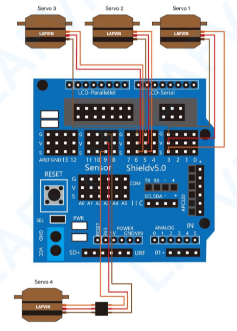
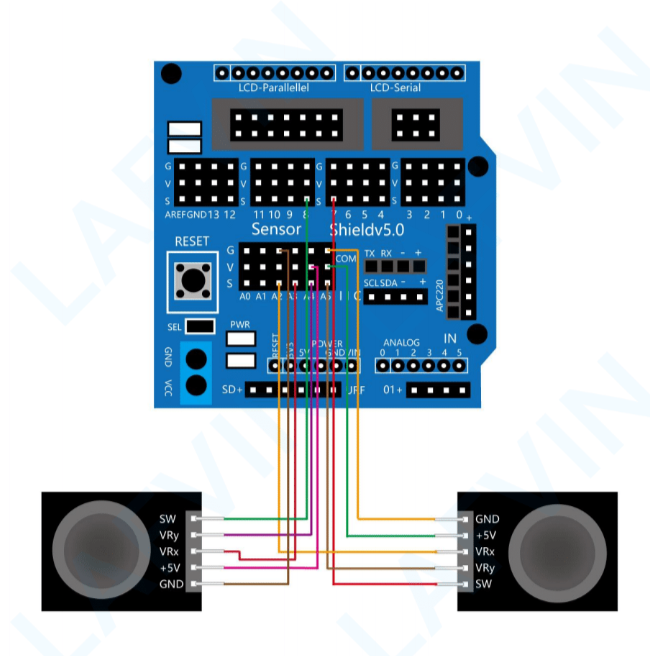
Schematics
Bill of Materials
| Part | Note | Price | Link |
|---|---|---|---|
| LAFVIN Mechanical Arm Claw Kit | Contains the arduino board, sensor shield, servo motors, wires, joystick, and acrylic parts for the robotic arm | $53.99 | Link |
| Raspberry Pi 4 Kit | Contains the Raspberry Pi 4 processor, cables to connect the Raspberry Pi to a power supply and monitor, and an SD card for the operating system | $119.99 | Link |
| Pi Camera | Camera that is controlled by the Raspberry Pi | $6.99 | Link |
| HM10 Bluetooth Module | Provides bluetooth capabilities to the robotic arm, allowing it to be controlled using a phone | $10.99 | Link |